The short answer
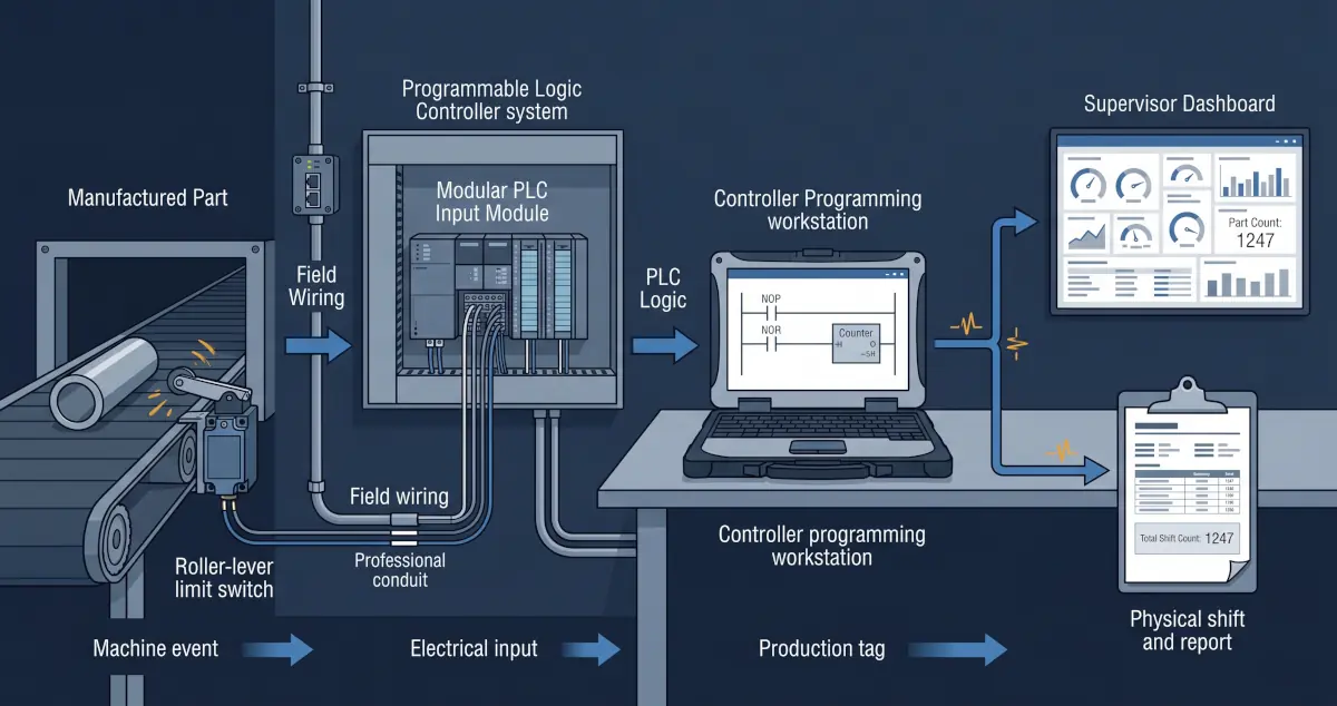
A production counter can begin with a limit switch connected to a PLC input, but accurate reporting requires more than adding one counter instruction. The complete system must define what event represents one finished unit, make sure the sensor produces one reliable transition per unit, integrate the count into the existing RSLogix or Studio 5000 program, preserve the correct totals, expose useful production tags, and move the data into a dashboard or report.
The sensor and PLC change must also respect machine safety, electrical requirements, scan timing, maintenance practices, and production ownership. A counter used for reporting must never be assumed to provide a safety function.
First define exactly what counts as one unit
Before selecting a sensor or opening the PLC project, operations and engineering need to agree on the event being measured. A part entering a machine, leaving a machine, passing inspection, entering packaging, and being added to inventory are different counts.
- What physical event means one completed unit?
- Can rejected or reworked parts activate the same sensor?
- Can one part activate the sensor more than once?
- What happens during manual operation, setup, or maintenance?
- Does the business need gross count, good count, reject count, or all three?
- Who is allowed to reset shift, batch, and lifetime totals?
A perfectly functioning counter can still produce misleading business data if it measures the wrong event.
Choose and install the sensing method
A roller-lever limit switch can be an effective option when a moving part reliably makes physical contact at a manageable speed. Other applications may be better served by a photoelectric sensor, proximity sensor, encoder, machine-state signal, or existing controller tag.
| Consideration | Why it matters |
|---|---|
| Mechanical repeatability | The part must activate the switch consistently without damaging the switch or product. |
| Contact bounce | A mechanical contact can transition several times during one activation unless the input or logic is filtered correctly. |
| Environment | Dust, moisture, vibration, washdown, temperature, and impact affect sensor selection and mounting. |
| Electrical compatibility | The signal type, voltage, input module, grounding, and protection must match the existing control system. |
| Event speed | A short pulse can be missed if it is faster than the input response and PLC scan can reliably detect. |
Electrical installation and machine modifications should be completed and reviewed by qualified personnel. The new counting circuit should be isolated from safety functions unless it is specifically engineered, validated, and approved as part of the safety system.
Integrate the count into the RSLogix program
Allen-Bradley controller projects may be maintained in legacy RSLogix 500, RSLogix 5000, or the current Studio 5000 Logix Designer environment, depending on the controller family and project age. The exact implementation must match the existing controller and programming standard.
Rockwell Automation documents that a Count Up instruction increments when its rung condition changes from false to true. That behaviour is useful for production counting, but it means the input must return false before the next item can be counted. Mechanical bounce, a stuck sensor, repeated machine motion, and scan timing must all be considered.
Typical logic responsibilities
- Convert the raw input into one validated production event.
- Filter or debounce the signal where required.
- Increment gross, good, reject, batch, shift, and lifetime totals as defined.
- Control reset permissions and record when a reset occurs.
- Handle power cycles, controller mode changes, and retained values deliberately.
- Expose count status, sensor health, and data-quality indicators for downstream systems.
When a standard PLC counter is not enough
If the pulse is too fast or too short relative to the input module and controller scan, a normal scanned input may miss events. The design may require an input filter adjustment, pulse-stretching method, high-speed counter module, encoder, or another hardware approach. The correct choice depends on the equipment and required accuracy.
Before any online edit or download, preserve a verified project backup, review the change with operations, understand controller ownership, and define a rollback plan and approved maintenance window.
Expose production data without weakening the control system
The reporting system should consume a small, clearly defined set of production data rather than unrestricted access to the controller program. Useful tags may include current count, previous shift count, target, rate, machine state, downtime reason, reject count, timestamp, and data-quality status.
Depending on the controller and architecture, data can be exposed through a controlled industrial gateway, SCADA or historian connection, approved EtherNet/IP integration, or controller-to-controller produced and consumed tags. Rockwell notes that produced and consumed tags use controller connections and require matching controller-scoped data types, so they should be designed intentionally rather than added casually.
Business reporting traffic should not be allowed to interfere with the machine-control path. Segment the network, restrict permissions, document the interface, and make reporting read-only wherever practical.
Turn the counter into useful production information
A live number on a screen is only the beginning. The value becomes operationally useful when it is given context and retained over time.
Current count, target, rate, machine state, and immediate production context.
Shift performance, downtime, rejects, variance, and trends across machines.
Scheduled exports linked to orders, inventory, quality, maintenance, or management reporting.
The reporting layer should preserve timestamps, define shift boundaries, handle communication loss, and distinguish a machine producing zero parts from a system that has stopped receiving trustworthy data.
For the architecture behind that reporting layer, read our guide to connecting PLC data to a production dashboard without disrupting the machine.
A practical implementation plan
- Observe the process. Confirm the exact physical event and failure modes with operators and maintenance.
- Review the control system. Identify the controller, input capacity, project version, network, scan requirements, and program ownership.
- Design the sensing method. Select, mount, wire, and test the sensor or reuse a trustworthy existing machine signal.
- Back up and change the PLC program. Add documented logic, validation, totals, resets, and data-quality tags through an approved change process.
- Expose a controlled data interface. Provide only the production information required by downstream systems.
- Build and validate reporting. Compare dashboard totals against real production across normal, reject, setup, and downtime scenarios.
- Document ownership. Record the sensor, wiring, logic, tags, reset procedures, network path, and recovery process.
Rugged Technology Services designs these complete paths through our industrial systems integration services in New Brunswick, from field device and PLC logic through dashboards, reports, and secure remote support.
Primary sources
Industrial control changes are site-specific. Sensor installation, electrical work, PLC modifications, and commissioning should be completed by qualified personnel using the facility's safety and change-control procedures.

About the author
JR
JR works across industrial systems integration, operational technology, embedded systems, Linux administration, and networking at Rugged Technology Services.
Read JR's profile